PC in Powermac G5 Enclosure

glay78

Senior Member
Joined
Jul 16, 2002
Messages
500
Reaction score
0
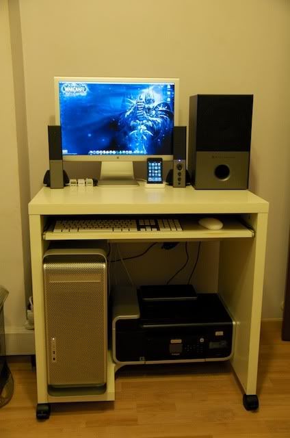
I posted this in VRZone, so sharing it here too.
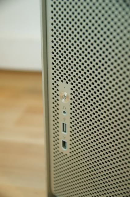
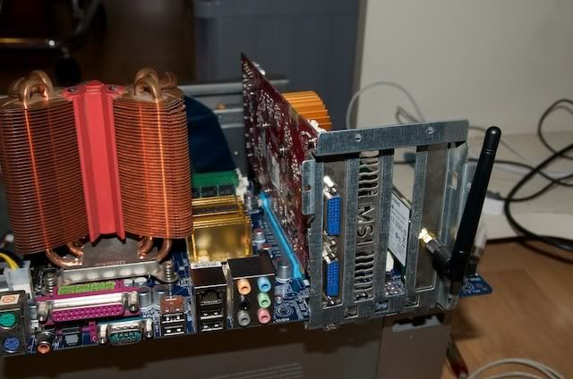
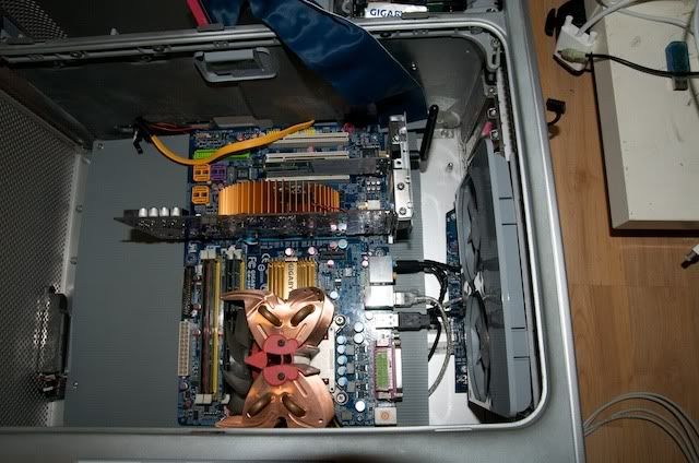
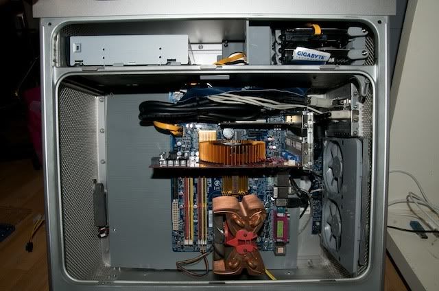
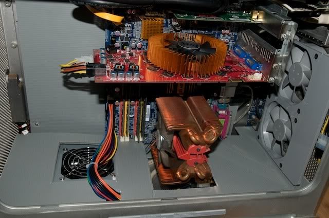
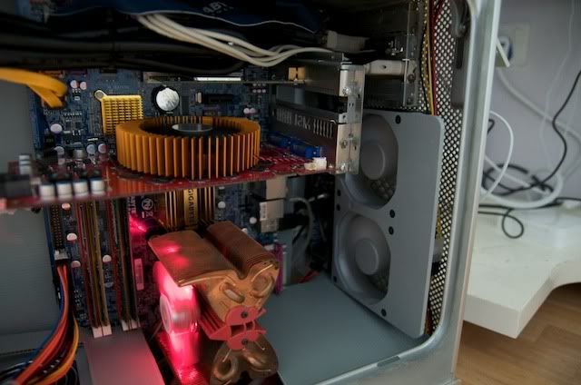
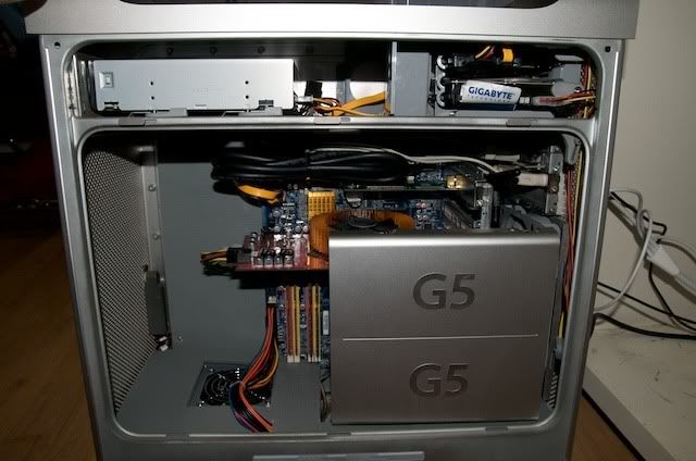
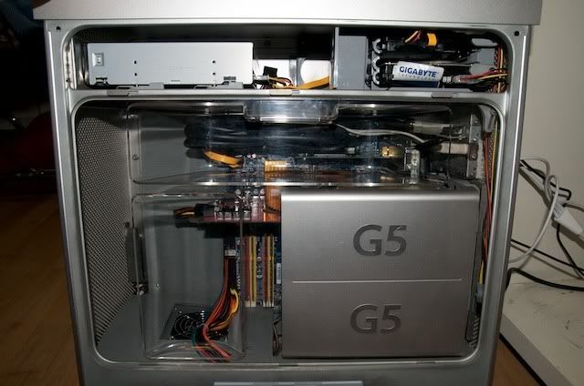
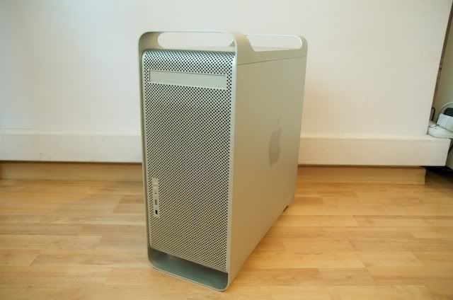
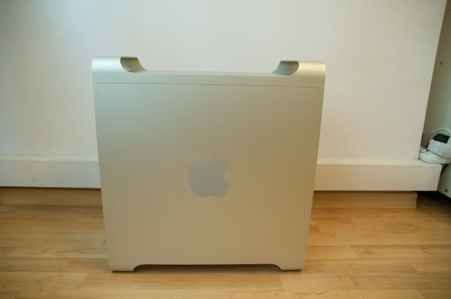
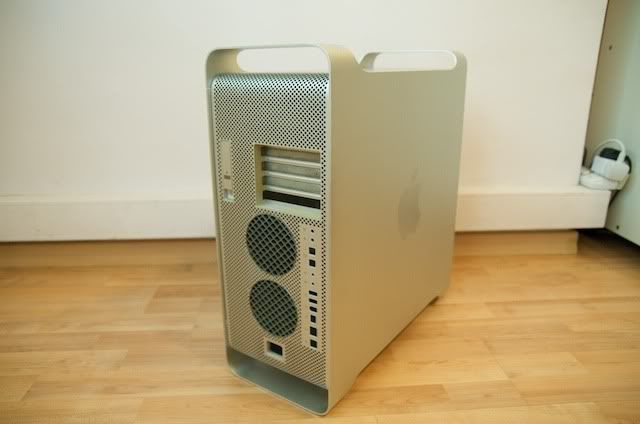
I love the Power Mac G5 and Mac Pro's enclosure, the aluminum finish and the design is so damn nice. Too bad Mac Pro is abit way out of my budget and Power Mac G5 are obsoleting soon as Intel processors are used in Macintosh nowadays, so the only way is to put my PC in an Apple desktop enclosure.

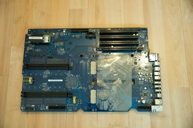
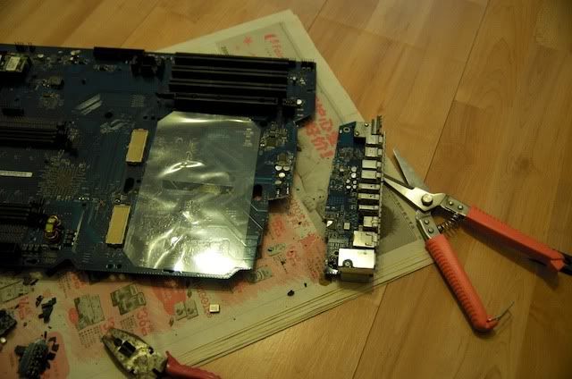
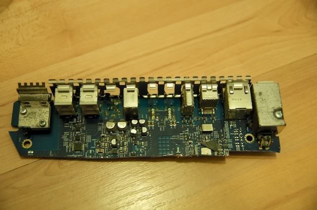
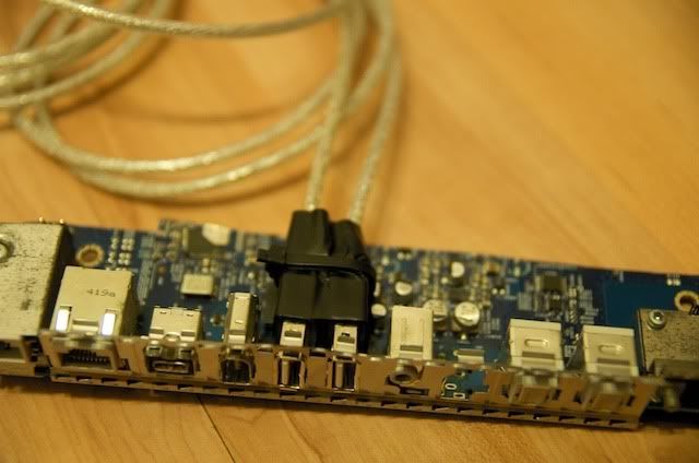
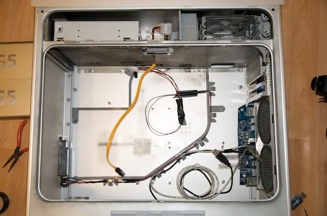
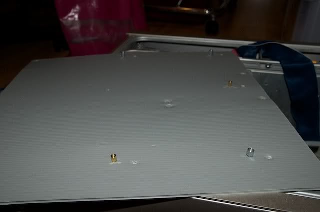
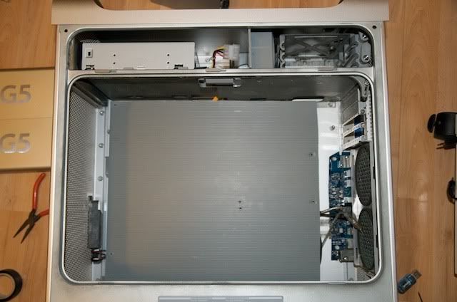
After some months of searching I found an empty case for sale because of the logic board failure so I managed to get the enclosure with the spoilt logic board and fans in the case.
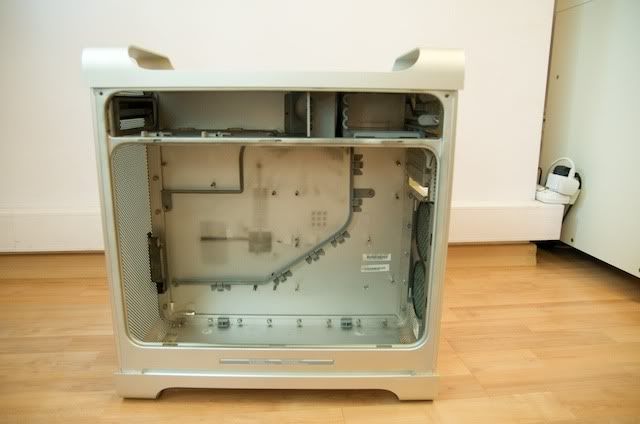
DSC_0099.jpg

DSC_0098.jpg

DSC_0102.jpg

DSC_0103.jpg
 

glay78

Senior Member
Joined
Jul 16, 2002
Messages
500
Reaction score
0
The spoilt logic board, which I will explain later why I need it

DSC_0097.jpg


My intention is to keep the outlook as original as possible even the rear where all the ports will still remain, I do not wish to cut the rear for the mobo I/O like other mods I've seen to fit an ATX or mATX board.

My PC is about 2yrs old. Below are the specs

Intel Core 2 Quad Q6600 2.4Ghz @ 3.0Ghz
Gigabyte GA 965P DS3
4 x 1GB Kingston DDR2 667mhz Ram
ZEROtherm BTF90 HSF
MSI nVidia 9600GT 512MB
Seagate 300GB IDE HDD
Seagate 320GB SATA HDD
LG 20x internal super multi DVD writer SATA
300w Mini PSU

The biggest challenge in this mod is to fit an ATX board inside while not cutting off the rear I/O portion of the case and also my aim is to preserve the inside look as close as original G5. Below is a picture of how the inside of G5 looks like

AppleMacintosh-Power-Mac-G5-tower1-kitchener-6fyvx.jpg
 

glay78

Senior Member
Joined
Jul 16, 2002
Messages
500
Reaction score
0
This is what most modders do when they fit a pc in a G5 case. Notice that the rear I/O portion is cut off.

back.jpeg


Even if I cut off the rear portion I will also have difficulty in fitting in an ATX board. So after some thinking and planning I got my ideas on how can I fit in.

OK lets start working. 1st take a look at the front connections. I found the pinout for this and I'm sure I can make all ports useable, however I do not use firewire so I will pass the firewire connection. I'm only able to tap the on/off button and power LED to work. For the headphone jack and USB I will need to try to squeeze the jumpers in inorder to tap out the connection.

DSC_0100.jpg
 

glay78

Senior Member
Joined
Jul 16, 2002
Messages
500
Reaction score
0
OK the spoilt logic board as I've mention, I will cut out the rear I/O portion out 1st.

DSC_0104.jpg


This is the finished product, but not done yet

DSC_0105.jpg


I will take out both the USB and the speaker out jack

DSC_0107.jpg
 

glay78

Senior Member
Joined
Jul 16, 2002
Messages
500
Reaction score
0
Fit in USB ext cables so that the other end connects to the mobo inside the case.

DSC_0115.jpg


Bought these from Sim Lim Tower, just connect the points using wire and checked connectivity using multimeter.

DSC_0253.jpg


Its done

DSC_0254.jpg


This end will go thru the case speaker hole and screw to tighten.

DSC_0255.jpg
 

glay78

Senior Member
Joined
Jul 16, 2002
Messages
500
Reaction score
0
The small part of the logic board is screwed to the case.

DSC_0117.jpg


This is how the rear looks like, check out the speaker output jack.

DSC_0256.jpg


Next will proceed to lay the cables. The power button and LED to the mobo, the SATA and IDE cables as well as the rear I/O cables.

DSC_0128.jpg
 

glay78

Senior Member
Joined
Jul 16, 2002
Messages
500
Reaction score
0
Next I moved on to the gfx output. I will be mounting the mobo inside of the case so the original PCI cards won't align to the case opening. So this is what I did.

Use an old nVidia FX5200 card from my old Power Mac G4

DSC_0109.jpg


Take out the metal plate, bought a both end female DVI plug and fit in. The other hold looks empty so I cut out the VGA port too.

DSC_0111.jpg


Mount it onto the plate and its done.

DSC_0112.jpg


Can guess what I'm up to? I will connect a DVI cable inside the case to one end of the female plug, so from the back of the case it looks like a gfx card fitted in.
 

glay78

Senior Member
Joined
Jul 16, 2002
Messages
500
Reaction score
0
Next is the mounting of the mobo in. As the standoff of the case do not fit a pc, I do not want to remove them so I used these cardboard, cut and mount onto the original Apple standoff then insert the mobo mounting to mount my ATX board.

DSC_0127.jpg


DSC_0258.jpg


DSC_0129.jpg
 

glay78

Senior Member
Joined
Jul 16, 2002
Messages
500
Reaction score
0
The mobo has a PCI slots backing behind so I can screw the PCI cards and secure them. Its cut off from my previous Power Mac G4 case.

DSC_0259.jpg


Mobo fitted in.

DSC_0263.jpg


Next I moved on to the DVI cables for the gfx card to the female DVI socket. Also added a 4 x USB bracket and plugged to my mobo. Notice DVDROM and HDD are in placed. The HDD are secured to the HDD bracket that comes with the case with lock.

DSC_0264.jpg
 

glay78

Senior Member
Joined
Jul 16, 2002
Messages
500
Reaction score
0
Next I will tap the pinout of the rear exhaust fan then plug to the molex connector of PSU. I set it to run at 7v which produce lesser noise as compared to 12v.

DSC_0271.jpg


Testing fan, it worked!!

DSC_0273.jpg
 

glay78

Senior Member
Joined
Jul 16, 2002
Messages
500
Reaction score
0
Lastly its almost done, the PSU is placed on the bottom of the case then I cut a cardboard to cover the messy cables :p

DSC_0266.jpg


DSC_0267.jpg


One final test to confirm fan working.

DSC_0274.jpg
 

glay78

Senior Member
Joined
Jul 16, 2002
Messages
500
Reaction score
0
Ok ready to cover up, fitting up the G5 processor cover. Hehe

DSC_0268.jpg


Cover up the plastic cover.

DSC_0269.jpg


I've yet to take a latest shot of the rear will do it when free.
 

glay78

Senior Member
Joined
Jul 16, 2002
Messages
500
Reaction score
0
Ok its up and running fine. Temp is 44deg on idle @3.0GHz.
I also installed Leopard on it. Running 10.5.8 with Apple Aluminum keyboard, Apple Mighty Mouse and 20" Apple Cinema Display. My customised Mac Pro :)

DSC_0125.jpg


There are few more things that I can do, to add in the front fan and make a better rear PSU socket. Don't really have much time recently will slowly do and update when done. Thanks for looking and if there are any more ideas to improve do let me know.
 

cueball1981

Supremacy Member
Joined
Dec 3, 2005
Messages
5,968
Reaction score
1
Excellent job.. the moment i saw the title.. i knew it you who post on VR some time ago.. just one world BEAUTIFUL
 

glay78

Senior Member
Joined
Jul 16, 2002
Messages
500
Reaction score
0
Excellent job.. the moment i saw the title.. i knew it you who post on VR some time ago.. just one world BEAUTIFUL

Thank you...your nick very familiar...i think we exchanged PM before but I cannot remember what isit regarding
 

lyfeforce

Senior Moderator
Senior Moderator
Joined
Dec 7, 2006
Messages
18,531
Reaction score
27
I'm very impressed. Good thinking and adaptation. A job well done.
 

glay78

Senior Member
Joined
Jul 16, 2002
Messages
500
Reaction score
0
I'm very impressed. Good thinking and adaptation. A job well done.

Thank you very much

Nice man! I like the i/o shield bit and the gfx card. Ingenious!

Thanks actually for the I/O shield ports I wanted to solder to the original ones on the G5 board but they were too tiny so in end I removed them and replaced with cables. The gfx idea took me quite a while. I kept thinking how can I mount in even when I'm showering, eating, driving and lying on bed :p

blasphemy.
but i am impressed

Thank you very much
 

Nickyrash

Junior Member
Joined
Nov 11, 2009
Messages
2
Reaction score
0
Thank you for your wonderfull information so that it would helps the other people to learn more about the computer cpu.
 
Important Forum Advisory Note
This forum is moderated by volunteer moderators who will react only to members' feedback on posts. Moderators are not employees or representatives of HWZ. Forum members and moderators are responsible for their own posts.

Please refer to our Community Guidelines and Standards, Terms of Service and Member T&Cs for more information.
Top